Highest quality standards are achieved through the implementations of latest technology, decades of experience and everlasting moral values , which have helped us to retain our customers as well as multiply them.
Features
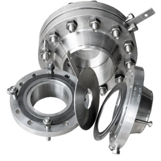
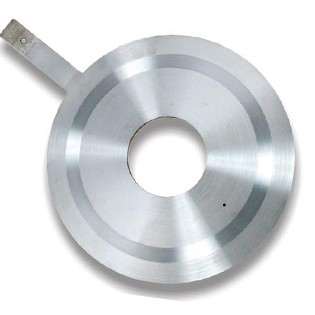
General Instruments orifice plate is a device used for measuring flow rate. Either a volumetric or mass flow rate may be determined, depending on the calculation associated with the it. It uses the same principle, namely Bernoulli's principle which states that there is a relationship between the pressure of the fluid and the velocity of the fluid. When the velocity increases, the pressure decreases and vice versa.
Features
The weldneck flange assembly is designed to transfer stresses to the pipe, thereby reducing high stress concentrations at the base of the flange. The pressure tappings are provided through the flange which are at a distance of 25.4mm (1") from the relevant face of the plate. Weldneck flanges are prefered since the joint between flange and pipe can be subjected to radiography, to ensure quality of welding joint.
The slip on flange has a low hub because the pipe slips into the flange prior to the welding. It is welded both from inside and out to provide sufficient strength and prevent leakage. The slip on flanges are bored slightly larger than the OD of the matching flange. SORF flanges are not preferred where pressure tapping through flange is required, since after welding in line blocks the tapping holes which need to be redrilled at site after welding in line.
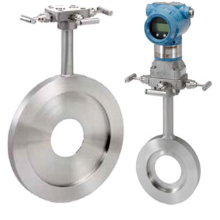
Orifice assembly with carrier raing and flange union is provided to facilitate pressure tapping, by means of corner tappings. This construction is generally used for lower sizes (less than 2"). However carrier rings can be used for higher line sizes also.
Features
The restriction orifices are used for reducing fluid pressure and are designed somewhat different from the orifice plates that are used for measuring flow rates. They are designed to slip between the piping flanges.
While single restriction orifices are often sufficient to meet the requirements, there are situations where limitations arise due to process conditions making the single restriction orifices unacceptable. In such situations, use of multiple restriction in series is a better solution.
The foremost consideration for the case of multiple restriction is the pressure drop. This applies whether or not the fluid is liquid or vapor/gas.Higher pressure drop implies higher velocities resulting in vibration and noise problems.
The other consideration is not just about maximum permitted pressure drop and this is particularly for gas flow. If the process condition indicates that critical flow will occur with the use of single restriction plate, care should be exercised to avoid operating well beyond the critical pressure drop. Critical implies a pressure drop across the device exceeding 50 percent of the absolute upstream pressure at which point sonic velocity is reached.
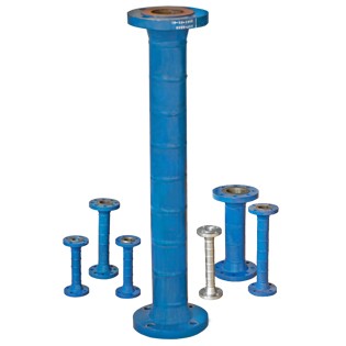
Construction of Multistage Orifice Assembly comprises of multiple restriction orifice plates separated by a distance of one pipe diameter and welded with the pipes in between them. End connection is either suitable for butt welding or with end flanges. IBR Form IIIC certificate can be provided as per requirement.
Features
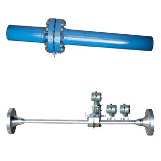
General Instruments Manufactured Integral Orifice Assemblies are another type of measuring flow device, which caters to the principle of maintaining constant reynolds number through out the process of media entering and processed and finally out of the assembly. This is possible with the precision manufactured device wherein the input flange, with pipe chamber, the orifice assembly and the outlet pipe chamber and the subsequent flange for the flange end connection, all shall be attributed to constant reynolds number.
The type of integral assemblies General Manufactures
a) Integral meter run assembly upto 2”
Features
Unique profile shape enables high flow rate turn down
Dual averaging for better accuracy
Suitable for Liquid, gas and steam flow measurement
Repeatability of measurement ± 0.1 %
Short upstream and downstream straight pipe lengths
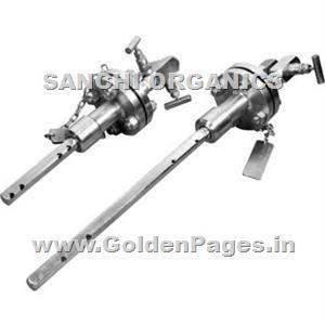
Long term accuracy unaffected by wear. Averaging pitot tubes are generally used for large line sizes or ducts where other primary devices become relatively expensive. Averaging Pitot tube comprises of following components:
Outer impact tube
Internal averaging tube
Low pressure chamber
Head
Features
Most flow meter technologies require significant and often unattainable upstream and downstream straight-run to meet and sustain specified accuracy. Similarly, most pump and compressor manufacturers recommend significant straight-run to ensure even flow into the pump to minimize wear and maximize service life.
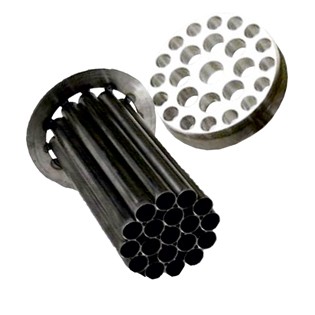
General flow straighteners / conditioners reduce straight-run requirements to just a few diameters. General flow straighteners / conditioners eliminate the flow distortion effects of elbows, pipe expansion or reductions, valves, dampeners and other disrupters to produce a swirl-free, symmetrical and repeatable flow profile to the flow meter, pump or other critical components.
Further, General flow conditioners have extremely low pressure drop, resulting in significant energy cost savings over alternative flow conditioning technologies.
General flow Straighteners / conditioners are available in straight-pipe runs, a unique 90° elbow and insertion panel designs for virtually any pipe, tube or duct size.
General flow conditioners and straighteners enhance accuracy for many flowmeter technologies
Flowmeters require a swirl-free repeatable and symmetric velocity profile to operate within stated accuracy specifications. Flow disturbances caused by ball valves, elbows, headers, and blowers for example may adversely affect a flowmeters accuracy.
There are two ways to mitigate flow disturbances.
1. Maintain sufficient straight run upstream of the meter.
2. Utilize General Elbow flow conditioners / straightner.
General flow conditioner's technology is ideally suited to work in various medias including gas, stream, liquids, slurries, sludges, hydrocarbons, and more. The General flow conditioner outperforms all other flow conditioning technologies with respect to minimal pressure loss, non-fouling design, and repeatable flow profiles. The following highlights summarize the advantages of using this technology with various flow metering.
We are leading Flow Straighteners Manufacturers and Flow Conditioner Manufacturers in Mumbai, India
Features
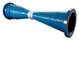
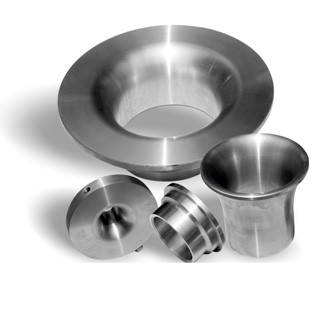
General Flow Nozzle is used in typically high-velocity, non- viscous, erosive flow. They are suitable for determining the flow rates of fluids at high temperature and high pressure.
General Flow Nozzles are erosion-resistant, consistently accurate and vir tually maintenance-free. They per form a wide variety of applications that include air, water, steam, gas, chemical substances and high temperature applications. The rounded design provides a more effective sweep-through of par ticles in the flow stream, which extends product life by reducing wear and potential damage. Flow Nozzles are manufactured in strict accordance with ASME MFC-3M, BS-1042 and ISO-5167 standards. For critical measurement applications, wet calibration at reputed flow laboratories can be offered. Also we have an IBR approval for our manufacturing unit hence we can provide IBR form IIIC cer tificate for flow nozzles. Flow Nozzles have a smooth elliptical inlet leading to a throat section with a sharp outlet. Restriction in the fluid flow causes a pressure drop, which relates to the flow rate by applying Bernoulli’s equation.The smooth inlet of the flow nozzle results in a higher coefficient of discharge than most other differential meters. This higher efficiency means greater flow capacity when compared to most other differential meters of the same size.
There are three types of Flow Nozzles
ISA 1932, with corner taps
ASME long radius, low beta ratio (0.20 < b < 0.5), with throat tap
ASME long radius, high beta ratio (0.25 < b < 0.8), with radius taps (D & D/2)
ASME long radius, low beta ratio Nozzle with throat taps is used in
steam turbine per formance test as per ASME PTC-6 code.
ISA-1932 nozzle can be mounted with carrier ring or in between
flanges with corner taps.
Long radius nozzle are normally with weld-in branch pipe with
radius taps.
To avoid welding of dissimilar metals, nozzles are also installed in the
pipe with holding ring.
Features
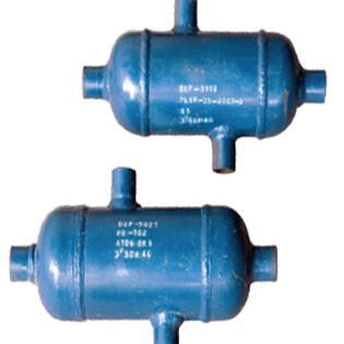
We manufacture complete range of condensate pots which requires in many process industries condensate pots are generally used for measurement of steam / vapor which condense to liquid state at the ambient temperature. These are also used to cool down very high temperature liquids and to maintain a constant liquid head above the instrument. These can be installed in both horizontal & vertical position. We manufacture these condensate pots as per customer's requirement and design in various sizes 2”, 3” and 4” etc. Condensate pots are manufactured in various grades of Carbon steel, Alloy steel & stainless steel. IBR Form IIIC certificate can be provided for condensate pots.
Features
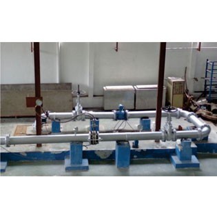
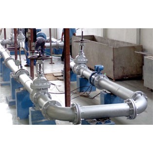
The orifice assembly or the flow control element, valve, is calibrated under fluid mechanics standards of ISO 5167 and IEC 60534 standards. The process and the procedure of the measuring flow calibration of the device and the design is as per the international standards applicable for volumetric and gravimetric conditions.
The flow calibration bench for upto 12” size, is applicable for pressure 2 rating upto 3 kg /cm g and for all ambient conditions. The testing media is water. The calibration unit is under free length or straight length as per the ISO standards for mounting in such conditions applicable for orifice assemblies with water as media and with calculated beta value to decide the free length for calibration of sensors. For valves, the condition is kept at ambient conditions with water and based on IEC 60534 standard the flow coefficient value of the valve is matched with desired flow rate applicable under differential pressure conditions, under applicable and available free or straight lengths.
The bench gets the water from an underground tank with an overall capacity of m3 which is having a magnetic level gauge mounted to check the level of water. The level in turn helps to clear the pressure applicable under the centrifugal pump which is mounted to the side to generate the desired and the requisite pressure for the flow assembly, either valve or orifice.
The differential pressure in the assembly is created by either manually adjusting the input pressure, with adjustable valves at the input line to the device for calibration or by pneumatically adjusting the variations through control pneumatic actuators adjusting to set points.
Features
Flow Calibration Test Bench
IBR Testing and Compatibility
Hydrotesting facility upto 400 kg/cm
Hydrotest rig upto 6" line size & pressure
PMI Testing Facility
Radiography Facility
PWHT Facility
O Cleaning Facility and Test Bench
Sand Blasting Machine
Painting Facility
2 Axis CNC Machines
3 Axis VMC machine
In-house welding facility with ARGON upto 80 kg/cm2 & ARC welding
Plasma cutting Machine upto 35 mm thickness
Lathe machines, upto 2.5 mtr plate OD
Drilling Machine
Grinding Machine
Cutting Machine
* To embrace new technologies and methods. * To give unsurpassed products and services to the clients. * To constantly look for improvement and changes.